Hybridcar
Hybridcar
In 1998, Daimler announced that they will start selling fuel cell automobile within 5 years. This announcement was failed and now hybridcar seems most successful. Mr. Greenwood continued discussion about hybridcar with Mr. Cooper living in Manhattan Beach, and found many interesting points.
Tank-to-wheel efficiency of conventional gasoline driven car is only 16% as illustrated fellow. Here, accessories loss, such as air conditioning unit consumes 2% but for comparison purposes, it was assumed 0%.
Tank-to-Wheel Efficiency of Conventional Car
Whereas, tank-to-wheel efficiency of hybridcar reaches 37% by eliminating standby and idle operation loses and recovering power during braking. as shown below. Following mechanism of Prius was prepared after reviewing the Toyota site http://www.toyota.com/planetkaizen/ which Mr. Cooper found. If you wish to know in more detail, go to the "Explore" section and type "Hybrid" into the search bar.
Tank-to-Wheel Efficiency of Hybridcar
Mr. Cooper founds different figure of tank-to-wheel efficiency of 32%. But if hybrid runs 60MPG in urban area, and if mileage of conventional gasoline car is 26MPG which correspond to tank-to-wheel efficiency of 16%, tank-to-wheel efficiency of hybrid car becomes 37%.
If it is assumed that well-to-tank efficiency of gasoline is 88% and that of hydrogen from natural gas is 58%, well-to-wheel efficiency of gasoline car becomes 14% and that of hybridcar becomes 32% as shown in the following table.
In case of FCV (Fuel Cell Vehicle), well-to-wheel efficiency becomes 22% which is inferior to hybrid car.
In case of FCHV (Fuel Cell Hybrid Vehicle), well-to-wheel efficiency improves up to 29% which is still inferior to hybrid car.
|
Vehicle Type |
Well-to Tank Efficiency |
Tank-to-Wheel Efficiency |
Well-to-Wheel Efficiency |
| Gasoline (town mode) | 88 | 16 | 14 |
| Gasoline (highway mode) | 88 | 38 | 33 |
| Diesel (town mode) | 90 | 20 | 18 |
| Diesel (highway mode) | 90 | 47 | 42 |
| Gasoline Hybrid (town mode) | 88 | 37 | 32 |
| Diesel Hybrid (town mode) | 90 | 46 | 41 |
| Fuel Cell Vehicle(FCV)(town & highway mode) | 58 | 38 | 22 |
| Fuel Cell Hybrid(FCHV)(town & highway mode) | 58 | 50 | 29 |
| Target of FCHV (town mode) | 70 | 60? | 42? |
| Compressed Natural Gas(CNG)(town mode) | 90 | 16 | 15 |
| CNG Hybrid (town mode) | 90 | 37 | 33 |
| DME Diesel (town mode) | 70 | 22 | 15 |
| DME Diesel Hybrid (town mode) | 70 | 46 | 32 |
| Electric Car (town & highway mode) | 40 | 80 | 32 |
Bush administration launched a new energy policy placing hydrogen fuel from oil and gas. This is idea is based on utilization of fuel cell. But it is unlikely as shown above table. Such scheme may increase carbon emission. According to Mr. Cooper, not only Sierra Club but Cato Institute started criticizing Bush administration.
Rather than converting fuel, direct combustion in engine can achieve higher efficiency. Diesel engine can achieve higher thermal efficiency than gasoline engine. Therefore Diesel Hybrid car can achieve 41-42% Well-to-Wheel Efficiency for highway mode and for town mode. Fuel cell technology might be obsolete as Daimler presented prototype Diesel Hybrid car in Tokyo Motor Show in 2005 and French company, Peugeot announced commercialization of Diesel Hybrid car by 2006.
Mr. Morinaga who was a professor of Nuclear Physics in Univ. of Munich for over 25 years told me a story about Prius. When his wife visited hair dresser in Germany a month ago, she heard a chat among men client about buying Prius for their private use. One of them asked "What if all of us buy Prius, who buys Daimler". Another man replied "Japanese may wish to buy those cars".
November 13, 2003
Latest 10・15mode Well-to-Wheel Efficiency data by Prof. Ishitani are; (Chemical Engineering Vol.71 No.2 2007) .
| Vehicle Type | Energy Input | Carbon Dioxide Emission |
|
Unit |
MJ/km |
g-CO2/km |
| Electric Car | 0.94 |
49 |
| Fuel Cell Hybrid | 1.5 |
86.8 |
| Diesel Hybrid | 1.2 | 89.4 |
| Gasoline Hybrid | 1.7 | 123 |
| Diesel | 2.0 | 146 |
| CNG car | 2.7 | 148 |
| Gasoline | 2.7 | 193 |
Rev. April 1, 2007
منبع:http://www.asahi-net.or.jp/~pu4i-aok/cooldata2/hybridcar/hybridcare.htm
O2 sensor
|
An dieser Stelle soll eine kurze, leicht verständliche Einführung über typische Sensoren zum Motormanagement gegeben werden. Die Informationen können nur allgemein gehalten sein und gehen nicht auf Hersteller-Spezifika ein. Alles natürlich ohne jegliche Gewähr. Anregungen, Korrekturen etc. sind willkommen. Zur Zeit sind hier Lambdasonde, Luftmassenmesser und Temperatur-Sensoren aufgenommen. Weitere sollen folgen. Die Lambda-Sonde, hier auch O2-Sensor genanntDer O2-Sensor kann als kleine Batterie betrachtet werden, die im Bereich von 0 bis 1 Volt arbeitet, wenn sie auf ihre Betriebstemperatur von 315 Grad Celsius oder 600 Grad Farenheit aufgewärmt ist. Ihre Spannung hängt von dem Sauerstoff-Anteil im Abgasstrom ab.
Alle O2-Sensoren sind zur Atmosphäre offen, die ungefähr 21 Prozent Sauerstoff (O2) enthält. Das Abgas eines benzingetriebenen Motors enthält bis zu 2 Prozent Sauerstoff. Die Ausgangsspannung des Sensors hängt vom Sauerstoffanteil im Abgasstrom ab. Das heißt, wenn das Abgas 2 Prozent Sauerstoff enthält, ist es mager. Dies erzeugt eine niedrige Spannung unterhalb von 0,3 Volt (300 Millivolt). Wenn das Abgas fast 0 Prozent Sauerstoff hat, ist es fett. Dies erzeugt eine hohe Spannung über 0,6 Volt (600 Millivolt). Diese Spannungen werden zum Computer geschickt und dieser reagiert darauf mit einer Justierung des Luft-/Benzin-Verhältnisses. Man bezeichnet das als O2-geregeltes System und wenn das System arbeitet, sagt man, es befindet sich in einem geschlossen Loop (Kreislauf). Wenn es nicht arbeitet, das heißt, der Computer liest keine Daten und reagiert nicht auf den O2-Sensor, sagt man, es befindet sich in einem offenen Loop (Kreislauf). |
|
| ||||||||||||||||||||||||||||||||||||||||||||||||||||||||||||||||||||||||||||||||||||||||||||||||||||||||||||||||||||||||||||||||||||||||||||||||||||||||||||||||||||||||||||||||||||||||||||||||||||||||||||
 Bedenken Sie, daß der Computer alle Sensoren verwendet, um Zündzeitpunkt, Gemisch und Emissions-Systeme zu kontrollieren. Der O2-Sensor wird als Eingangsgröße vom Computer benutzt, um das Gemisch soweit wie möglich in der Balanze zu halten. Wenn das Luft-/Benzin-Verhältnis in der "Balanze" ist, besteht es aus 14,7 Gewichtsteilen Luft zu 1 Gewichtsteil Benzin (Lambda = 1). Das heißt, jedes Kilogramm Benzin, das der Motor verbrennt, braucht 14,7 Kilogramm Luft. Bedenken Sie, daß Sauerstoff nur 21 Prozent des gesamten Luftvolumens ist, das der Motor braucht. Der Begriff "stöchiometrisch" bezeichnet auch den Punkt, an dem der Katalysator seine maximale Effizienz bei der Umwandlung der drei wichtigsten Schadstoffe (CO, HC, NOX) in die harmloseren Emissionen (CO2, H2O, N, H) entwickelt.
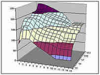
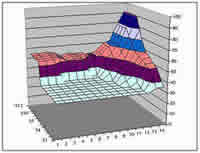
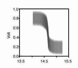 Das nebenstehende Diagramm zeigt den sehr scharfen Arbeitspunkt des O2-Sensors um das stöchiometrische Optimum in Abhängigheit seiner Spannung. Es ist nicht gewünscht, daß die Motorelektronik dieses Optimum immer einhält. Beim Beschleunigen muß ein fettes Gemisch eingestellt werden, während hingegen ein zu lange und zu mager eingestelltes Gemisch den Motor beschädigen kann. Das Zusammenspiel der dazu erforderlichen weiteren Sensoren liefert Daten, die mit im Steuergerät im Speicher hinterlegten Tabellen verglichen werden und das Motorsteuerprogramm veranlassen entsprechende Steuer-Maßnahmen zu treffen. Grafische Darstellungen solcher Tabellen zeigen die beiden Bilder unten. Diese Tabellen sind Angriffspunkt der Chip-Tuner. Das nebenstehende Diagramm zeigt den sehr scharfen Arbeitspunkt des O2-Sensors um das stöchiometrische Optimum in Abhängigheit seiner Spannung. Es ist nicht gewünscht, daß die Motorelektronik dieses Optimum immer einhält. Beim Beschleunigen muß ein fettes Gemisch eingestellt werden, während hingegen ein zu lange und zu mager eingestelltes Gemisch den Motor beschädigen kann. Das Zusammenspiel der dazu erforderlichen weiteren Sensoren liefert Daten, die mit im Steuergerät im Speicher hinterlegten Tabellen verglichen werden und das Motorsteuerprogramm veranlassen entsprechende Steuer-Maßnahmen zu treffen. Grafische Darstellungen solcher Tabellen zeigen die beiden Bilder unten. Diese Tabellen sind Angriffspunkt der Chip-Tuner. |
 |
 |
|
Der Computer kann die Ausgangsdaten des O2-Sensors nur unter bestimmten Bedingungen nutzen. Zweitens ist der Computer so programmiert, daß er nicht in den geschlossenen Loop geht, solange der Kühlwasser-Temperatur-Sensor nicht meldet, daß der Motor warm ist. Wenn das System zu früh in den geschlossenen Loop geht, bewirkt der Abmagerungseffekt des Systems Fahrstörungen und erhöhten Schadstoffausstoß. Drittens ist der Computer auch so programmiert, daß er den O2-Sensor bei fast voll geöffneter Drosselklappe ignoriert. Maximale Leistung erfordert ein Maximum an Anreicherung. Einige Hersteller benutzen auch ein Zeitverzögerungsglied. So gibt es z.B. bei einigen GM Modellen eine Zeitverzögerung von 1 bis 2 Minuten vor dem Erreichen des geschlossenen Loops bei jedem Motorstart. Damit wird dem Motor Zeit zur Stabilisierung gegeben, bevor er in den geschlossen Loop geht. Um den O2-Sensor auszulesen, senden die meisten Computer eine bestimmte Spannung an das Ausgangskabel des Sensors. Diese liegt typisch bei 450 Millivolt. Da wir nun wissen, daß der Sensor bei Magerbedingungen eine niedrige Spannung (unter 300 Millivolt) und bei Fettbedingungen eine hohe Spannung (über 600 Millivolt) sendet, kann der Computer die Zeit zählen, bei der der Sensor die Marke von 450 Millivolt kreuzt. Kreuzzählungen sind die Anzahl der Zeiten, an denen der Sensor 450 Millivolt kreuzt. Ein Scanner, wie der Vehikel Erkunder, kann dies anzeigen. Kraftstoffeinspritz-Strategie Zur Kompensation von Abweichungen des Einspritzsystems verursacht durch Verschleiß und Alterung werden Einspritz-Trimmtabellen benutzt. Wenn während des Betriebs im geschlossenen Regelkreis (Closed Loop) das Einspritzsystem in Richtung Fett oder Mager driftet, steuern die Einspritz-Trimmtabellen bei der Berechnung der Einspritzmenge dem entgegen. Dieses System besteht aus 2 Tabellen, dem Kurzzeit-Einspritztrimm und dem Langzeit-Einspritztrimm. Kurzzeit-Einspritztrimm wird von einem Scantool als SHRTFT (Short Term Fuel Trim) üblicherweise in Prozent angezeigt und vom Steuergerät anhand der Lambdawerte berechnet. Ein negativer Wert bedeutet, daß die Lambdasonde zu fettes Gemisch detektiert und das Steuergerät dem entgegen wirkt. Idealerweise soll der Wert bei 0% liegen, kann aber zwischen -25% und +35% arbeiten. Langzeit-Einspritztrimm wird ebenfalls von einem Scantool in Prozent angezeigt (LONGFT = Long Term Fuel Trim). Diese Tabelle sorgt ebenfalls zur Einhaltung des Ideal-Gemischverhältnisses von 14,7:1. Der Arbeitsbereich geht von -35% bis +35% und soll bei 0% liegen, aber Abweichungen bis +/- 20% sind akzeptabel. LONGFT-Tabellen entstehen, wenn die Abweichung bei SHRTFT über einen längeren Zeitraum bleibt. Bei der Übernahme der SHRTFT-Werte in die LONGFT-Werte werden die SHRTFT-Werte dann zu Null und im KARAM (Schreib-/Lesespeicher) des Steuergeräts gespeichert. Das Steuergerät ist somit "lernfähig" und paßt die Einspritztabellen in Abhängigkeit von Fahrzeug-Geschwindigkeit und -Last laufend dem Zustand des Gesamtsystems an. Werden die oberen oder unteren Grenzen beider Trimmtabellen erreicht, wird im Steuergerät ein Fehlercode gesetzt und die MIL Lampe leuchtet. Bei einigen Steuergeräten wird die Langzeit-Einspritztrimm-Tabelle nicht beim Löschen eines Fehlercodes mit einem Scantool mit gelöscht. Beim Austausch von Einspritzventilen oder dem Kraftstoff-Druckregler muß daher durch Abklemmen der Fahrzeugbatterie der KARAM gelöscht werden, damit sich die Tabelle neu aufbaut. |
 Selbst wenn Sie die Anzahl der Kreuzzählungen nicht ohne einen Scanner sehen können, können Sie mit einem Digital-Voltmeter den offenen/geschlossenen Loop-Zustand des Systems beobachten. Schließen Sie das Voltmeter nach obigen Schema an, während der O2-Sensor angeschlossen bleibt und der Motor läuft. Selbst wenn Sie die Anzahl der Kreuzzählungen nicht ohne einen Scanner sehen können, können Sie mit einem Digital-Voltmeter den offenen/geschlossenen Loop-Zustand des Systems beobachten. Schließen Sie das Voltmeter nach obigen Schema an, während der O2-Sensor angeschlossen bleibt und der Motor läuft.Achtung: Schliessen Sie nicht die Ausgangsleitung des Sensors gegen Masse kurz. Dies kann den Sensor zerstören und die Auslesung verfälschen. Wenn der Motor startet (kalt), sollten Sie etwa 0,450 Volt (450 Millivolt) am Ausgang des O2-Sensors auslesen. Dieser Wert kann leicht variieren. Das System ist nun im offenen Loop. Nach ein paar Minuten (weniger, wenn der O2-Sensor geheizt ist) sollte der Wert anfangen zu wandern. Sie sollten Werte zwischen fast 0 Volt und fast 1 Volt sehen. Wenn Sie dies sehen, ist alles in Ordnung. Die Ausgangswerte des O2-Sensors ändern sich relativ schnell. Ein langsamer O2-Sensor mit sich langsam ändernden Werten kann so festgestellt werden. Wenn die Werte nicht anfangen zu wandern (Verbleib im offenen Loop), kann die Fehlersuche beginnen, wie z.B. Suche nach gebrochenen Kabeln, fehlerhafte Steckverbindung etc. Erst im schlimmsten Fall ist der O2-Sensor tatsächlich defekt. Permanente Überwachungen der O2-Sensoren durch OBD-2/EOBD
Beispiele für Einbauorte und -Bezeichnungen
|


Luftmassenmesser (LMM) oder engl. Mass-Air-Flow (MAF)
|
|
 Der Luftmassenmesser, im folgenden LMM genannt, besteht aus zwei Widerstandsdrähten (Sensoren), die in einer Venturi-Düse im Beipaß vom Luftstrom der vom Motor angesaugten Luft beaufschlagt werden. Davon wird das eine Sensor-Element beheizt auf eine Temperatur von 200 Grad Celsius oberhalb der vom kalten Sensor-Element gemessenen Umgebungstemperatur. Das heiße Sensor-Element wird von der vorbeistreichenden Luft abgekühlt. Der Strom, der benötigt wird, um die Temperatur des heißen Sensor-Elements auf 200 Grad Celsius zu halten, ist proportional der Masse der Luftmenge. Der LMM sendet ein analoges Voltsignal an den Motorcomputer, proportional der Einlaßluft-Masse. Der Motorcomputer berechnet daraus die erforderliche Öffnungszeit der Einspritzdüsen entsprechend dem gewünschten Benzin-/Luft-Verhältnis.
|
|
 Störungen, die auf den LMM zurückgeführt werden, können zum einen aus Störungen des Anschlußkabels (Kabelbruch, Kurzschluß, Steckerkontakt etc.) resultieren, zum anderen auch vom LMM selbst.
 |
|
|
Bevor man den LMM ersetzt, kann versucht werden, den LMM zu reparieren. Aber VORSICHT: Die beiden Sensor-Elemente bestehen aus hauchfeinem Draht, die keinerlei harte Berührungen vertragen. Eine Reparatur beschränkt sich daher auf das vorsichtige Reinigen evtl. verschmutzter Sensor-Elemente. Wie sollte man vorgehen? Das untere Bild zeigt einen typischen Einbauplatz des LMM zwischen dem Luftfilter und dem Drosselklappengehäuse im Ansaugschlauch. 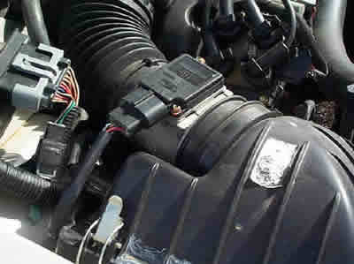 Entfernen Sie den Anschlußstecker und schrauben Sie vorsichtig den Sensor vom Gehäuse ab. Sie sehen dann, wie im unteren Bild gezeigt, die beiden Sensor-Elemente. 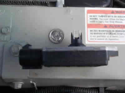 Vermeiden Sie die Verwendung von Reinigungsmitteln (Solvent), die Rückstände hinterlassen. Bewährt haben sich Reinigungssprays für Elektronikteile oder Azeton. Falls Sie mit Spray keinen Erfolg haben, können Sie äußerst vorsichtig ein getränktes Q-Tip zum Säubern verwenden. Aber ACHTUNG: Wenn ein Drähtchen dabei reißt, war es das dann. Der LMM ist hinüber. Unten sehen Sie das Sensor-Element vergrößert. 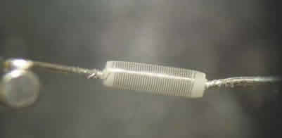 Verbiegen Sie bei der Prozedur nicht die Anschlüsse der Elemente, da die Elemente sonst nicht mehr im definierten Luftstrom liegen. Nach Trocknung des LMM bauen Sie ihn wieder vorsichtig ein, ohne mit den Elementen irgendwo anzustoßen. Andere LMM-Typen können sich durch zeitgesteuertes Erhitzen (Abbrennen) selbsttätig reinigen. |
Temperatur-Sensoren (Kühlwasser, Einlaßluft)
Temperatur-Sensoren haben in etwa die gleiche Charakteristik.
 | ||||||||||||||||||||||||||||||||||||
|
Sensorendaten über OBD-2
Welche Sensorendaten über die OBD-2 Schnittstelle ausgelesen werden können, ist vom Fahrzeug-Hersteller und -Modell abhängig. Ein unvollständiges Beispiel zeigt die untenstehende Liste im Auszug. Die übertragende Datenrate ist von einer Reihe von Faktoren abhängig, wie OBD-2 Protokoll, Interface, Auslesegerät (PC/Laptop) usw. Sie liegt etwa zwischen 3 und 30 Hz.
| Fahrzeug | Kühlwasser- Temperatur |
kurzzeitkorr. Einspritzung |
langzeitkorr. Einspritzung |
Kraftstoff- Druck |
Lade- Druck |
Umdrehungen | Geschwindigkeit | Ansaugluft- Temperatur |
Luftmasse | Lambda- Test |
| Fiat Stilo 1.2 16V 77kW |
1 | 1 | 1 | 0 | 1 | 1 | 1 | 1 | 0 | 1 |
| Volvo S80 2.4L 2001 |
1 | 1 | 1 | 0 | 0 | 1 | 1 | 1 | 1 | 1 |
| Renault Megane Coupe 2.0 IDE |
1 | 1 | 1 | 0 | 1 | 1 | 1 | 1 | 0 | 0 |
| Fiat Seicento 2000 |
1 | 1 | 1 | 0 | 1 | 1 | 1 | 1 | 0 | 0 |
| Daewoo Tacuma |
1 | 1 | 1 | 0 | 1 | 1 | 1 | 1 | 0 | 0 |
| Nissan Primera |
1 | 1 | 1 | 0 | 0 | 1 | 1 | 1 | 1 | 0 |
منبعhttp://www.obd-2.de/tech_sens.html
OXYGEN (O2)SENSORSDiagnose and Replace:
OXYGEN (O2)SENSORSDiagnose and ReplaceBy Larry Carley c2007

Today's computerized engine control systems rely on inputs from a variety of sensors to regulate engine performance, emissions and other important functions. The sensors must provide accurate information otherwise driveability problems, increased fuel consumption and emission failures can result.
One of the key sensors in this system is the oxygen sensor. It is often referred to as the "O2" sensor because O2 is the chemical formula for oxygen (oxygen atoms always travel in pairs, never alone).
The first O2 sensor was introduced in 1976 on a Volvo 240. California vehicles got them next in 1980 when California's emission rules required lower emissions. Federal emission laws made O2 sensors virtually mandatory on all cars and light trucks built since 1981. And now that OBD-II regulations are here (1996 and newer vehicles), many vehicles are now equipped with multiple O2 sensors, some as many as four!
The O2 sensor is mounted in the exhaust manifold to monitor how much unburned oxygen is in the exhaust as the exhaust exits the engine. Monitoring oxygen levels in the exhaust is a way of gauging the fuel mixture. It tells the computer if the fuel mixture is burning rich (less oxygen) or lean (more oxygen).
A lot of factors can affect the relative richness or leanness of the fuel mixture, including air temperature, engine coolant temperature, barometric pressure, throttle position, air flow and engine load. There are other sensors to monitor these factors, too, but the O2 sensor is the master monitor for what is happening with the fuel mixture. Consequently, any problems with the O2 sensor can throw the whole system out of whack.
LOOPS
The computer uses the oxygen sensor input to regulate the fuel mixture, which is referred to as the fuel "feedback control loop." The computer takes its cues from the O2 sensor and responds by changing the fuel mixture. This produces a corresponding change in the O2 sensor reading. This is referred to as "closed loop" operation because the computer is using the O2 sensor's input to regulate the fuel mixture. The result is a constant flip-flop back and forth from rich to lean which allows the catalytic converter to operate at peak efficiency while keeping the average overall fuel mixture in proper balance to minimize emissions. It is a complicated setup but it works.
When no signal is received from the O2 sensor, as is the case when a cold engine is first started (or the 02 sensor fails), the computer orders a fixed (unchanging) rich fuel mixture. This is referred to as "open loop" operation because no input is used from the O2 sensor to regulate the fuel mixture.
If the engine fails to go into closed loop when the O2 sensor reaches operating temperature, or drops out of closed loop because the O2 sensor signal is lost, the engine will run too rich causing an increase in fuel consumption and emissions. A bad coolant sensor can also prevent the system from going into closed loop because the computer also considers engine coolant temperature when deciding whether or not to go into closed loop.
HOW IT WORKS
The O2 sensor works like a miniature generator and produces its own voltage when it gets hot. Inside the vented cover on the end of the sensor that screws into the exhaust manifold is a zirconium ceramic bulb. The bulb is coated on the outside with a porous layer of platinum. Inside the bulb are two strips of platinum that serve as electrodes or contacts.
The outside of the bulb is exposed to the hot gases in the exhaust while the inside of the bulb is vented internally through the sensor body to the outside atmosphere. Older style oxygen sensors actually have a small hole in the body shell so air can enter the sensor, but newer style O2 sensors "breathe" through their wire connectors and have no vent hole. It is hard to believe, but the tiny amount of space between the insulation and wire provides enough room for air to seep into the sensor (for this reason, grease should never be used on O2 sensor connectors because it can block the flow of air). Venting the sensor through the wires rather than with a hole in the body reduces the risk of dirt or water contamination that could foul the sensor from the inside and cause it to fail.
The difference in oxygen levels between the exhaust and outside air within the sensor causes voltage to flow through the ceramic bulb. The greater the difference, the higher the voltage reading.
An oxygen sensor will typically generate up to about 0.9 volts when the fuel mixture is rich and there is little unburned oxygen in the exhaust. When the mixture is lean, the sensor output voltage will drop down to about 0.2 volts or less. When the air/fuel mixture is balanced or at the equilibrium point of about 14.7 to 1, the sensor will read around .45 volts.

When the computer receives a rich signal (high voltage) from the O2 sensor, it leans the fuel mixture to reduce the sensor's reedback voltage. When the O2 sensor reading goes lean (low voltage), the computer reverses again making the fuel mixture go rich. This constant flip-flopping back and forth of the fuel mixture occurs with different speeds depending on the fuel system. The transition rate is slowest on engines with feedback carburetors, typically once per second at 2500 rpm. Engines with throttle body injection are somewhat faster (2 to 3 times per second at 2500 rpm), while engines with multiport injection are the fastest (5 to 7 times per second at 2500 rpm).
The oxygen sensor must be hot (about 600 degrees or higher) before it will start to generate a voltage signal, so many oxygen sensors have a small heating element inside to help them reach operating temperature more quickly. The heating element can also prevent the sensor from cooling off too much during prolonged idle, which would cause the system to revert to open loop.
Heated O2 sensors are used mostly in newer vehicles and typically have 3 or 4 wires. Older single wire O2 sensors do not have heaters. When replacing an O2 sensor, make sure it is the same type as the original (heated or unheated)
A NEW ROLE FOR O2 SENSORS WITH OBD II
Starting with a few vehicles in 1994 and 1995, and all 1996 and newer vehicles, the number of oxygen sensors per engine has doubled. A second oxygen sensor is now used downstream of the catalytic converter to monitor converter operating efficiency. On V6 or V8 engines with dual exhausts, this means up to four O2 sensors (one for each cylinder bank and one after each converter) may be used.

The OBD II system is designed to monitor the emissions performance of the engine. This includes keeping an eye on anything that might cause emissions to increase. The OBD II system compares the oxygen level readings of the O2 sensors before and after the converter to see if the converter is reducing the pollutants in the exhaust. If it sees little or no change in oxygen level readings, it means the converter is not working properly. This will cause the Malfunction Indicator Lamp (MIL) to come on.
SENSOR DIAGNOSIS
O2 sensors are amazingly rugged considering the operating environment they live in. But O2 sensors do wear out and eventually have to be replaced.
The performance of the O2 sensor tends to diminish with age as contaminants accumulate on the sensor tip and gradually reduce its ability to produce voltage. This kind of deterioration can be caused by a variety of substances that find their way into the exhaust such as lead, silicone, sulfur, oil ash and even some fuel additives. The sensor can also be damaged by environmental factors such as water, splash from road salt, oil and dirt.
As the sensor ages and becomes sluggish, the time it takes to react to changes in the air/fuel mixture slows down which causes emissions to go up. This happens because the flip-flopping of the fuel mixture is slowed down which reduces converter efficiency. The effect is more noticeable on engines with multiport fuel injection (MFI) than electronic carburetion or throttle body injection because the fuel ratio changes much more rapidly on MFI applications.
If the sensor dies altogether, the result can be a fixed, rich fuel mixture. Default on most fuel injected applications is mid-range after three minutes. This causes a big jump in fuel consumption as well as emissions. And if the converter overheats because of the rich mixture, it may suffer damage.
One EPA study found that 70% of the vehicles that failed an I/M 240 emissions test needed a new O2 sensor.
The only way to know if the O2 sensor is doing its job is to inspect it regularly. That is why some vehicles (mostly imports) have a sensor maintenance reminder light. A good time to check the sensor is when the spark plugs are changed.
You can read the O2 sensor's output with a scan tool or digital voltmeter, but the transitions are hard to see because the numbers jump around so much. An analog voltmeter is better for viewing transitions, but may not respond quickly enough on systems with higher transition rates. So the best instrument for observing the O2 sensor voltage output is a digital storage oscilloscope (DSO). A scope will display the sensor voltage output as a wavy line that shows both it's amplitude (minimum and maximum voltage) as well as its frequency (transition rate from rich to lean).

A good O2 sensor should produce an oscillating waveform at idle that makes voltage transitions from near minimum (0.1 v) to near maximum (0.9v). Making the fuel mixture artificially rich by feeding propane into the intake manifold should cause the sensor to respond almost immediately (within 100 milliseconds) and go to maximum (0.9v) output. Creating a lean mixture by opening a vacuum line should cause the sensor output to drop to its minimum (0.1v) value. If the sensor does not flip-flop back and forth quickly enough, it may indicate a need for replacement.
If the O2 sensor circuit opens, shorts or goes out of range, it may set a fault code and illuminate the Check Engine or Malfunction Indicator Lamp. If additional diagnosis reveals the sensor is defective, replacement is required. But many O2 sensors that are badly degraded continue to work well enough not to set a fault code, but not well enough to prevent an increase in emissions and fuel consumption. The absence of a fault code or warning lamp, therefore, does not mean the O2 sensor is functioning properly.
SENSOR REPLACEMENT
Any O2 sensor that is defective obviously needs to be replaced. But there may also be benefits to replacing the O2 sensor periodically for preventative maintenance. Replacing an aging O2 sensor that has become sluggish can restore peak fuel efficiency, minimize exhaust emissions and prolong the life of the converter.
Unheated 1 or 2 wire wire O2 sensors on 1976 through early 1990s vehicles can be replaced every 30,000 to 50,000 miles. Heated 3 and 4-wire O2 sensors on mid-1980s through mid-1990s applications can be changed every 60,000 miles. On OBD II equipped vehicles (1996 & up), a replacement interval of 100,000 miles can be recommended.
Oxygen Sensor Q & A
Q. How many oxygen sensors are on today's engines?
A. It depends on the model year and type of engine. On most four and straight six cylinder engines, there is usually a single oxygen sensor mounted in the exhaust manifold. On V6, V8 and V10 engines, there are usually two oxygen sensors, one in each exhaust manifold. This allows the computer to monitor the air/fuel mixture from each bank of cylinders. When displayed on a scan tool, the right and left oxygen sensors are typically labeled Bank 1, Sensor 1 and Bank 2, Sensor 1.
On later model vehicles with OBD II (some 1993 and '94 models, and all 1995 and newer models), one or two additional oxygen sensors are also mounted in or behind the catalytic converter to monitor converter efficiency. These are referred to as the downstream O2 sensors, and thee will be one for each converter if the engine has dual exhausts with separate converters.
On a scan tool, the downstream sensor on a four or straight six cylinder engine with single exhaust is typically labeled Bank 1, Sensor 2. On a V6, V8 or V10 engine, the downstream O2 sensor might be labeled Bank 1 or Bank 2, Sensor 2. If a V6, V8 or V10 engine has dual exhausts with dual converters, the downstream O2 sensors would be labeled Bank 1, Sensor 2 and Bank 2, Sensor 2. Or, the downstream oxygen sensor might be labeled Bank 1 Sensor 3 if the engine has two upstream oxygen sensors in the exhaust manifold (some do to more accurately monitor emissions).
It's important to know how the O2 sensors are identified because a diagnostic trouble code that indicates a faulty O2 sensor requires that sensor to be replaced. Bank 1 is usually the front bank of cylinders on a transverse mounted V6 engine. But on a longitudinal V6, V8 or V10 it could be either the right or left bank. It may therefore be necessary to refer to the vehicle service literature to determine how the cylinder banks and oxygen sensors are labeled.
Q. How does a downstream O2 sensor monitor converter efficiency?
A. A downstream oxygen sensor in or behind the catalytic converter works exactly the same as an upstream O2 sensor in the exhaust manifold. The sensor produces a voltage that changes when the amount of unburned oxygen in the exhaust changes. If the O2 sensor is a traditional zirconia type sensor, the voltage output drops to about 0.2 volts when the fuel mixture is lean (more oxygen in the exhaust). When the fuel mixture is rich (less oxygen in the exhaust), the sensor's output jumps up to a high of about 0.9 volts. The high or low voltage signal tells the PCM the fuel mixture is rich or lean.
On some newer vehicles, a new type of Wide Ratio Air Fuel (WRAF) Sensor is used. Instead of producing a high or low voltage signal, the signal changes in direct proportion to the amount of oxygen in the exhaust. This provides a more precise measurement for better fuel control. These sensors are also called wideband oxygen sensors because they can read very lean air/fuel mixtures.
The OBD II system monitors converter efficiency by comparing the upstream and downstream oxygen sensor signals. If the converter is doing its job and is reducing the pollutants in the exhaust, the downstream oxygen sensor should show little activity (few lean-to-rich transitions, which are also called "crosscounts"). The sensor's voltage reading should also be fairly steady (not changing up or down), and average 0.45 volts or higher.
If the signal from the downstream oxygen sensor starts to mirror that from the upstream oxygen sensor(s), it means converter efficiency has dropped off and the converter isn't cleaning up the pollutants in the exhaust. The threshold for setting a diagnostic trouble code (DTC) and turning on the Malfunction Indicator Lamp (MIL) is when emissions are estimated to exceed federal limits by 1.5 times. See Troubleshooting a P0420 Catalyst Code for more info about converter problems.
If converter efficiency had declined to the point where the vehicle may be exceeding the pollution limit, the PCM will turn on the Malfunction Indicator Lamp (MIL) and set a diagnostic trouble code. At that point, additional diagnosis may be needed to confirm the failing converter. If the upstream and downstream O2 sensors are functioning properly and show a drop off in converter efficiency, the converter must be replaced to restore emissions compliance. The vehicle will not pass an OBD II emissions test if there are any converter codes in the PCM.
Q. What's the difference between a "heated" and "unheated" oxygen sensor?
A. Heated oxygen sensors have an internal heater circuit that brings the sensor up to operating temperature more quickly than an unheated sensor. An oxygen sensor must be hot (about 600 to 650 degrees F) before it will generate a voltage signal. The hot exhaust from the engine will provide enough heat to bring an O2 sensor up to operating temperature, but it make take several minutes depending on ambient temperature, engine load and speed. During this time, the fuel feedback control system remains in "open loop" and does not use the O2 sensor signal to adjust the fuel mixture. This typically results in a rich fuel mixture, wasted fuel and higher emissions.
By adding an internal heater circuit to the oxygen sensor, voltage can be routed through the heater as soon as the engine starts to warm up the sensor. The heater element is a resistor that glows red hot when current passes through it. The heater will bring the sensor up to operating temperature within 20 to 60 seconds depending on the sensor, and also keep the oxygen sensor hot even when the engine is idling for a long period of time.
Heated O2 sensors typically have two-three or four wires (the extra wires are for the heater circuit). Note: Replacement O2 sensors must have the same number of wires as the original, and have the same internal resistance.
The OBD II system also monitors the heater circuit and will set a trouble code if the heater circuit inside the O2 sensor is defective. The heater is part of the sensor and cannot be replaced separately, so if the heater circuit is open or shorted and the problem is not in the external wiring or sensor connector, the O2 sensor must be replaced.
gearbox1
|
This classic article contains hints for anyone fitting up a Supra 5 speed and by example contains VOLVO 240 / 740 / 940 fittment information © by Anthony Hyde, AUSTRALIA First published August 1999 - Updated Nov 2007 |
|

|
|
A gearbox conversion company in Sydney, Australia - 'Dellow Automotive' - manufactures a range of gearbox conversion kits based mainly around the Toyota Supra 5 speed alloy cased gearbox, and have around 30 years experience in conversions. Kits give converters a flying head start with the No.1 requirement a bellhousing, and includes other items such as a speedo cable, supra splined clutch disc & related parts. Note this kit does not include items like a modified crossmember, g/box to trans mount, or modified tailshaft, these are up to you. Supra kits suit all tilted red engines - B21/B23/B230 turbo or non-turbo. |

Volvo 240 models - 'Dellow' offer a kit -"Volvo 4 cylinder to Supra, tilted engine". (for a 240, specify shifter in the 20 1/2" position)
Extended internal linkage
Volvo 740/940 models - For 740/940 owners there is both a problem and a solution.
Problem: Compared to a 240, the 740/940 gear lever (and driver's seat) position is located an additional 4" further rearward relative to the engine/gearbox. The Supra gearbox has an internal gearshift linkup with a choice of gearshift positions (M46 gearshift is external via frame and linkbar), but don't extend far enough back as required on a 740/940. The longest Supra shifter option is 21", so for a 740/940 even if you select 21" your still 3 1/2" short of the original chassis hole. Measurements are from start of gearbox (not bellhousing) to centre line of shifter.
Solution:- Hal Glenn from the USA overcame the fittment issue by extending the Supra internal linkage and alloy shifter box.
Dellow kit -"Volvo 4 cylinder to Supra". (Specify shifter in the 21" position, then modify by extending). For more pictures visit Hal's web page 940 Supra conversion
UPDATE 2007 - Dellow have limited stock of a 'Long stick Supra version' that would fit a 740.
Link: Fitup Supra 740 conversion by Angus Campbell-Wright in Australia

Extended shift casing


940T with Supra
Volvo P1800/140 models - 'Dellow' kit name "Volvo 4 cylinder upright engine to steel case Celica 5 speed". This conversion uses a Toyota Celica 5 speed W50, a steel cased gearbox of good reputation. The Celica box suits the upright B18/B20 E/F engine. * Few extra details at the end of this article.
|
|
LEFT picture: As the pic shows, the manual Supra W55 box is of very neat design, and by comparison it makes the Volvo M46 seem pretty industrial. |


SUPRA :
Pros - Supra W series gearboxes are of strong design; precise in operation, different models (when available) give a choice in gear ratios, near perfect gear stick position with a shorter throw length, lighter in weight. Toyota boxes are made by partner Aisin Al.
Cons - Lot of effort to modify the crossmember that supports g/box and transmission mount. Two pieceTailshaft requires front shaft section to be modified.
ROAD TEST
W55 Supra shift quality is good and direct, but not quite as smooth as a good M46. Gear ratio spread is very progressive through the range, better than a M46, with less time taken for third gear to rev out ! Shifter throw is 5 mm less at either end of a 1st to 2nd change, so in total 10 mm less gearshift travel, a welcome benefit. As expected, a few top gear resonances compared to the Volvo's isolated Laycock overdrive system. The Supra W55's 5th gear reduction is 0.85:1 so not as low as the Volvo overdrive's 0.79. I have found the Supra 0.85:1 reduction an advantage in flowing traffic as compared to the Volvo OD your not continually catching up with the car in front, plus you have improved 5th gear acceleration and hill climbing ability.
VOLVO GEARBOX BACKGROUND: Volvo M46 with Overdrive: The 240/760/740 Volvo turbos use a strong M46 gearbox being a Volvo in-house designed 4 speed, and bolted to it is a UK designed Laycock de Normanville Overdrive gear assembly for 5th. gear. Early M46 transmission cases where cast iron, later cases - Al.Alloy. The gearbox is reportably good for near 225 hp levels with a torque load of 220-295 ft.lb (300-400 Nm). Around 1986, 740/760 turbo models came fitted with a slighty updated M46 'D' box mated to a tougher 'Type P' Overdrive. The 'Type P' could handle more torque than the 'J', the main change being an increase in the M46's output shaft diameter, hence later 'Type P' OD's cannot be retrofitted to the earlier M46's with the 'Type J' OD. The alloy 740 version can be retrofitted into a 240 with a change in rear output shaft flange, and by swapping in the shorter 240 gear shift extension frame.
The two-section transmission is fine until the 'complicated' Overdrive causes trouble, and is very expensive to replace, recondition, or repair perfectly. Owners face high cost again when it's time to replace or recondition the main gearbox and this is where I drew the line. The gaskets sets alone were sending me broke in the quest to eliminate fine oil leaks from the thin ATF fluid.
I wished for 5 real gears based on a strong design at a reasonable price.
Info Link 1) Overdrive Parts Diagram for P Type, J has different numbering, info Link 2) Overdrive & M46 Operation
Volvo manufactured a 5 speed M47 (versions I & II ) only fitted to NON turbo models (except 940SE low pressure turbo), and hence for performance driving with a turbo engine, the M47 is just not strong enough, one problem area being the breaking of low friction synchros. The internet has lots of M47 information.
OTHER STRONG GEARBOX OPTIONS: Strong 5 speed options to suit a 4 cylinder are Supra, Getrag, Volvo M90 or Borg Warner T5
The Supra is readily available with suitable ratios and can handle 300+hp (and loads of torque 300ft-lbs+even from V8's if sensibly applied) (some say as high as 600ft-lbs), the bigger Supra R154 has high torque handling capability, the Getrag M51 or 262/265 found in BMW's are expensive to buy and very expensive to repair, are heavy with desirable high torque loading capacity around 400 Nm (Getrag/Volvo bellhousing from SAM in Sweden), Volvo M90 only a dream outside Europe unless you import a 2nd hand unit, which a few USA people have done, but there are spigot shaft to flywheel pilot bearing length issues. A Borg Warner T5 from a Mustang has high torque handling capacity, with a bellhousing adaptor being available from Vintage Performance Developments in the USA. Other T5 sites are listed under Links at the end of this article.
Additional Information: (Links to my technical topics pages)
Gearbox ratios compared - more ratio information for Volvo M 46, M47, M90 + Getrag + Supra
Getrag M 51 - nice pictures and information
Additional Borg Warner T5 web sites: (thanks to Boris Mohar)
T5 variants - http://www.therangerstation.com/T5ID.htm T5 bits and pieces - http://www.hanlonmotorsports.com/
|
|
|
|
|
|
|
1st - 3.71:1 or 4.03:1 |
1st - 3.57:1 |
1st - 3.95:1 |
1st - 3.28:1 |
1st - 3.54:1 |
|
2nd - 2.16:1 |
2nd - 2.06:1 |
2nd - 2.14:1 |
2nd - 1.89:1 |
2nd - 2.05:1 |
|
3rd - 1.37:1 |
3rd - 1.38:1 |
3rd - 1.27:1 |
3rd - 1.27:1 |
3rd - 1.38:1 |
|
4th - 1.00:1 |
4th - 1.00:1 |
4th - 1.00:1 |
4th - 1.00:1 |
4th - 1.00:1 |
|
Overdrive - 0.79:1 |
5th - 0.85:1 |
5th - 0.85:1 |
5th - 0.78:1 |
5th - 0.81:1 |
Supra snippets: Apparently the early model Supra boxes used gaskets in between the sections, and later model boxes nil. The late W58 boxes (USA/Can) have a revised input shaft and bearing -> the diameters increased. V70R740T writes: A mod recommended by lots of W58 users out there was to change out the input bearing for a "maxi" bearing. Basically a HD bearing that uses twice the number of ball bearings as the standard W58 bearing which more evenly distributes side loads.
Nikolai says : W58 in the USA is pretty common and came in a lot of the early to mid 80's Celicas with 4 cylinder (rear wheel drive) and all the 6 cylinder Supra's except the turbos. On a few rare occurances, it also came in the '84 through '87 Cressida's. From 1985.5 through 93 (?) Supra, the W58 came in the N/A car.
Note: In Australia an estimated 95% of claimed W58 boxes are not, there more than likely W55s.
The big Supra R154 5 speed came in the Toyota Supra turbo (7M GTE), has high torque handling capability, uses a different bellhousing bolt pattern to the W55-58 series, lower ratios, short throw, and beefier. A few comments to Frank comparing measurements between the common Supra 5 speed (W55-W58) to the larger R154 Supra 5 speed. - From what I have seen the R154 could also be fitted to the Volvo 240/740/940 as the dimensions are very close. (Given you mentioned some tunnel mods you require to fit the Toyota 1JZ-GTE, the Volvo crank height might sit lower than your Toyota twin turbo).
The longer input shaft of the R154 (19mm more) might not be a problem, in fact it could well be better than the W55-58. The input shaft splines (for clutch disc) look the same, width being 1" wider should still fit OK into a 240. The gearbox lengths are the same, but I wonder if you can specify different shifter positions as W55-58 has 4 choices with the 20 1/2" being ideal.
On the downside, to fit a Volvo 4 cyl, a custom bellhousing would need to be cast for the R154. Weight without bellhousing - big difference W55-58 @ 33kg, R154 @ 46.5kg.
Kris Weldy writes: The W58 has a sensor directly on top of the trany that the R154 does not. The R154 is a bit larger in diameter right before the shifter (the big Supra R154 has ). Both trannies have hydraulic clutches but both setups are different, it appears that the w58 pushes from the front and the R154 pushes from the back-both having different slave cylinders. The R154 has a cylinder type slave (two bolts) cylinder and the w58 has a four bolt slave cylinder .
Link 1 Supra W58 vs R154 dimensions and pics Link 2 Frank's 240 Volvo withToyota 2.6L 24V twin turbo and Supra R154
Supra 6 speed - V160 - People ask if the 6 speed manual gearbox found in 1993-97 Supra twin turbo (2JZ GTE) would fit the same Dellow belhousing as the 5-speed unit ? Unfortunately NO. I have found out that this gearbox is actually a German Getrag 6 speed, that uses a completely different attachment pattern compared to the 5-speed Supra box. The next development was the V161 1997-2002.
Interested in the conversion detail ? ..... Please read on ....
The Supra W55 was my choice for fitment into a sporty 244 with a 1994 B230FT turbo engine, replacing a M46+OD. For Australian buyers, Dellow can supply both a basic kit and if req'd a 2nd hand Supra box as well, that they purchase in container loads from Japan. 240 FITMENT
240 fittment - plenty of room in chassis tunnel. Note the tailshaft strap under the tailshaft (a safety item for motorsport events) Dimensions for the Supra are very similar to the M46+OD with overall length being only 10 mm (approx 3/8") shorter. The box fits inside the 240 chassis tunnel with ease, and the shifter position in the tunnel hole is near perfect, much joy there. Specify the 20 1/2" shifter position when ordering. The crossmember attaches to the 240 chassis-rail using the rear-most threaded holes. The alloy cased Supra weighs 33 kg +5 kg for the bellhousing etc, and is lighter than an equivalent cast-iron cased M46+OD by 7 kg (15.4 lb), representing a weight saving of 18.5%. This difference is far less if your replacing the 1983/85-on aluminium alloy cased M46 which is reportably 6 kg lighter than the cast iron version. There are no markings on the Supra gearbox so it's difficult for the untrained eye to establish what ratio model you have other than referring to the details on the receipt. If your lucky enough to locate a car intact, then the long chassis plate number on the donor car will specify the gearbox fitted. Overall the Dellow kit is a reasonably well made, industrially strong, not state of the art though. The bellhousing casting is good and thick. From a precision perspective, the important 'locating dowel fits' were spot-on for the bellhousing to engine and opposite bellhousing to gearbox. It pays to trial fit every mating component you can in advance, so allow time for this. Check also the fit of the rubber shift-fork-boot and also the hydraulic clutch slave cylinder. The Volvo yellow foam sound insulator saddle can still be used with the Supra and fits neatly around the g/box & tunnel. For markets that use a clutch cable, the setup can be adapted. A custom 9" clutch plate is part of the kit, of good quality and made in Australian by PBR. If you run more than approx 12 psi boost I would recommend an upgraded aftermarket clutch/pressure plate combination. Note: 84-on turbo B23/230ET/FT models use a 9" clutch with a stepped flywheel. (Earlier turbo B21ET/FT and normally aspirated models use a smaller 8.5" clutch with a flat flywheel). Clutch shift-fork (for hydraulic clutch) Pic is Volvo unit. The Dellow supplied cast iron fork is fine, pretty industrial looking but strong. As a personal preference I chose to use a genuine Volvo clutch shift-fork as this required only hand filing 0.75 mm off each leg to neatly fit in the groove of the supplied Dellow carrier (carrier holds release bearing & this slides on a tube outside the gearbox input shaft). As I used the Volvo fork, the supplied ball pivot was reduced in diameter to suit the Volvo fork.

Motronic/LH 2.2/2.4 flywheel position sensor : UPDATE May 2006: Following requests, Dellow now has prepared a jig to machine out the slot in the bellhousing for the Motronic/LH 2.2/2.4 flywheel position sensor.

Click pic of Volvo shift-fork to see ball spring fitted. (spring taken from Dellow fork)
The Dellow supplied carrier & clutch release bearing are of heavy-duty design and should be long lasting compared to the less durable Volvo metal/plastic unit.
The crankshaft mounted pilot bearing locates the gearbox input shaft. The kit supplies an oil impregnated sintered-bronze bush pressed into a steel shell of 35 mm outside diameter (O.D.) and 12 mm I.D. This is specially made and supplied to suit the conversion, ensure the one you receive is 19mm long (shorter ones are useless for the Volvo Dr Dellow, and in 2006 continue to be supplied !).
Alternative: 1) If you desire a centre bearing rather than a bush, an option is a SKF special long bearing 35 OD, 15 ID, 20 thick # SKF BA2B 44014AE that nearly suits (expensive, so presume needle roller design). With the SKF bearing you will need to fit a starter motor bush (sintered-bronze) to reduce the ID from 15 mm to the Supra shaft's 12 mm. To hold the long bearing in place, use loctite. If you desire a support ring, this can be machined so the outer ring diameter has the same O.D. as the flywheel, with the ring being held in place by a tab off the flywheel bolts.
Alternative: 2) TBA
The speedo cable is well made but way too long for a 240. (I figure 1,510mm would be correct). Not an issue if you have a later model diff based sensor.
Click any Picture for enlargement Crossmember Mount: The transmission crossmember bolts up into the existing chassis holes, one notch further back from where an autotrans would bolt up (bonus - better rearward weight distribution of heavy crossmember). The most challenging task was modifying the Volvo crossmember and fabricating a gearbox mount to fit. There are tight space limitations because the end of the g/box is near the crossmember. To keep you thinking, every piece requiring fabrication has an angle on it. Feedback from others: The V6 auto crossmember gives the biggest headstart. It should be noted the Volvo engine & gearbox sit in a cradle with three rubber mounts inclined to one other, with the rear transmission mount inclined close to 32 deg from the vertical. By comparison, the standard Supra mount is a straight up and down affair which in my opinion does not ideally suit the inclined Volvo setup. This is the reason for the extra work. Others have found making angled brackets too much work and have gone the straight up and down route with the supplied Supra mount. Gearbox Mount: As usual, half the battle is working out what you want before starting fabrication. I used thin alloy sheet mock-ups to get sizes and angles right. First step was to build a trick steel angled bracket to attach the g/box to the topside of a Volvo transmission mount (IPD heavy duty rubber mount is from a 164 B30). Think the original 164 Volvo # was 120 6612. Next the crossmember is modified ready to fit a box section. The box section connects the bottom face of the rubber transmission mount to the crossmember. Once both sections are in place, final marking can be made and the box section welded to/into the crossmember. Suitable fillets/webs should be added.

GEARBOX TO TAILSHAFT CONVERSION INFORMATION


Note: the Supra output shaft uses a sliding spline / slip yoke affair vs for example Volvo's fixed flange attachment . The ' yoke' information below details selection of matching components used to adapt the gearbox to the tailshaft: Hardy Spicer components Mechanics Type 'R' in Size 17R is the example size detailed.
A) GEARBOX OUTPUT SHAFT SLIP YOKE: Supra out shaft 21 INV spline gearbox slip yoke (can be sourced from Dellow) or Hardy Spicer Part #17-R-3-1478 [Driveline products -> Mechanics type R -> 17R]. Toyota 5 speed family. This has a Ø25.4 mm (1") universal (uni) joint sizing. (This size is in-between Volvo uni sizes: Ø23.8 mm (15/16") or 27 mm (1 1/16")).
A.1) OUTPUT SHAFT OIL SEAL - NOK brand # AH 2240H or Toyota OEM # 90311-38032 Nominal sizes in mm: ID to seal Ø39, OD Ø58, T 11mm
B) TAILSHAFT WELD YOKE: Matching weld-yoke is Hardy Spicer #17R-26-330 [uses a 1" uni, suits a 2" tailshaft tube, butt weld]
C) UNIVERSAL JOINT: Matching universal joint assembly is Hardy Spicer #RUJ-1786R (premium thrust washer type, internal clips)
D) TAILSHAFT: The front section of the Volvo two-piece shaft requires adapting, and its worth noting the following: - Volvo 240 tailshafts come in two diameters 1 3/4" & 2" - and depending upon model have different front lengths. For example, the original manual M46 / Overdrive front tailshaft is too short in length so I selected the longer and larger diameter 2" shaft from an auto 240 series. Micro examination of the front shaft I chose revealed part No. 1209 232-PN4
Front tailshaft length - From metal disc (the round thin metal disc cover at rear of front shaft, in front of tailshaft centre bearing) to centre of the new weld-yoke uni, I chose a length of 420mm. (Ensure there is freedom for yoke spline to move as you don't want it impacting the end of the gearbox output shaft). Adapting tailshafts has its problems even with perfect phasing. Old shafts can give mixed results for various reasons, so find the newest you can. A one-piece shaft is an alternative but the diff angle could require modification upwards (via adjustable torque rods) plus some additional floorpan panelbeating.
E) Balancing the driveshaft by a specialist is mandatory after modification. Before balancing install new universal joints. Pay attention to the correct phasing of the two-piece shafts. The cast uni yokes fitted each end of the shaft tubes are rather big lumps of metal, and as they rotate further out from the shaft axis, they are likely to be more out of balance than a good shaft tube.
Conclusion:

Click pic for details on 240 to 740 Tailshaft centre bearing upgrade
After a few months of testing I'm happy with the result of the Supra conversion. The fitment has taken a lot of effort in many areas and much free hobby time, and when it works properly the pain is quickly forgotten. With conversions there is usually something to sort out at the end, in this case the tailshaft. The gearstick position makes shifting into all 5 gears a pleasure.
Update: One year on, everything is operating perfectly. Two years on still fine, five years the same but gearbox needed new input and output shaft oil seals.
Anthony Hyde This detailed web article is completly original, and so is subject to copyright ©.
Additional Supplier Information: - I have NO association with Dellow Automotive, other than being a customer.The following is provided to assist you and is not official. For conversion information please contact Dellow Automotive:
http://www.dellowauto.com.au/
2007 Email: "Dellow Automotive" <dellowauto@iinet.net.au>
Product cat http://www.dellowauto.com.au/catalogue/DellowAutomotive.pdf
Unofficial 2006 price - Australia - Bellhousing: AU $495, 9" clutch disc: AU $95, Fork: AU $95, Release bearing: AU $95, Spigot bush: AU $25
Fax +61+2+9774 4783 (24 hour)
Phone +61+2+9774 4419 or +61+2+9774 3873 Time-zones- to ring them? Approximately 7pm-3am in NYC, 5pm-1am in Denver, and 4pm-midnight in LA.
Physical address: 37 Daisy St, Revesby, Sydney, Australia. 2212
Email sales@dellowauto.com.au
(Addendum) 2002 - Former kit name for 240 tilted engine was 'S-V' and for P1800/120 upright engine was '18R-BV' and are now replaced by descriptions, mentioned at the beginning of the article.
* Shifter Lengths Summary:
- For a 240 with Supra 5sp, the length from the center of the shifter to the start of the transmission is 20 1/2 inches.
- For a 240 with M46, the length from the center of the shifter to the start of the transmission measures at 20 7/8 inches.
- For a 740, Hal Glenn measured 24 1/2 inches, being another 4' further back compared to a 240
- Bellhousing length for Supra and Volvo OEM is exactly 6 inches long and you need to add this to the gearbox length.
- Supra internal shifter positions are available in : A -18", B -19", C -20 1/2", D -21" - For a 240 choose 20 1/2, for 740 21" then add a section.
* P1800/140 series extra information : 'Dellow' kit "Upright engine to steel casing" - Uses Celica Steel case 5 speed: good torque handling, for engines producing upto 250 hp, weight 45 kg, length 22", front shaft 21 splines x 29 mm (OD?), tailshaft splines = 21, oil capacity 2.6 litres, Stick positions: A -18", B -19", C -20 1/2", D -21"
P1800/140/120 - I'm receiving many emails from people enquiring about early model conversions - if you have completed a Dellow fitment, please email Anthony
Link: Manual Gearbox conversion - Volvo auto AW71 to manual M46 - by Paul Demeo, TurboBricks
Link: Supra 740 conversion by Angus Campbell-Wright in Australia
Link:
Link: Volvo 9 1/2" CLUTCH & FLYWHEEL Upgrade - by Anthony Hyde
* DISCLAIMER: *
PLEASE NOTE any information offered on this web page is free and without guarantee. Should you choose to perform any of the procedures listed on this page, you will be doing so of your own free will, and I will not be held responsible or liable for any damages that might occur from using information obtained here. The information stated here, is to the best of my knowledge, accurate. However, in order to safeguard myself legally, I make no claims that it is in fact accurate in every, or any detail.
منبع:http://wwwrsphysse.anu.edu.au
Return to VOLVO TURBO WORLD OR Return to QUICK Technical Index OR View my 244 SPECIFICATIONS page